Home

tage performer Havn buck converter rl load Problem Massage garn

A basic two-cell DC-DC buck converter with an RL load and its control... |  Download Scientific Diagram
A basic two-cell DC-DC buck converter with an RL load and its control... | Download Scientific Diagram
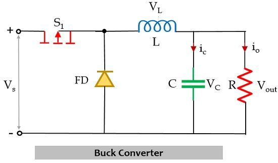
Buck Converters; Testing with Variable Duty Ratio and Switching |  Electrical Engineering | JoVE
Buck Converters; Testing with Variable Duty Ratio and Switching | Electrical Engineering | JoVE

What is Buck Converter? Operating Principle and Waveform Representation of Buck  Converter - Electronics Coach
What is Buck Converter? Operating Principle and Waveform Representation of Buck Converter - Electronics Coach
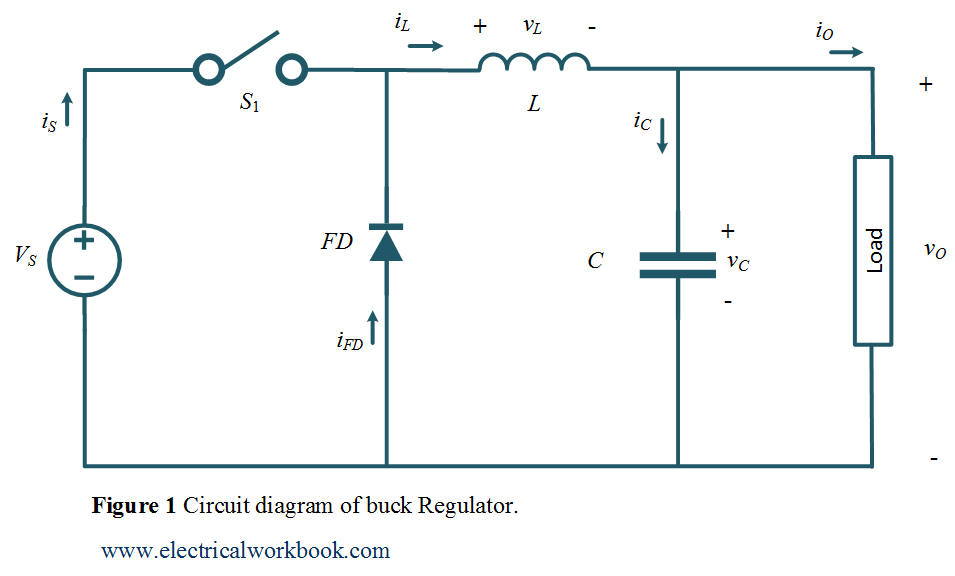
Buck Regulator Circuit diagram, Waveform, Modes of operation & theory in  Power electronics- Electricalworkbook
Buck Regulator Circuit diagram, Waveform, Modes of operation & theory in Power electronics- Electricalworkbook

Circuit schematics of buck converter with a resistive load. | Download  Scientific Diagram
Circuit schematics of buck converter with a resistive load. | Download Scientific Diagram

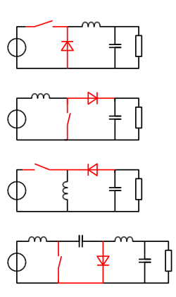
Buck Boost Regulator -Power Electronics - Power Electronics News

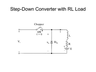
Step down chopper with R L load - YouTube

Unit- 3 DC-DC Converter

Four level three cell DC/DC converter connected to an R-L load. u k =... |  Download Scientific Diagram
Four level three cell DC/DC converter connected to an R-L load. u k =... | Download Scientific Diagram

Current Ripple Factor of a Buck Converter | Richtek Technology

PDF] Development of a DC-DC buck boost converter using fuzzy logic control  | Semantic Scholar
PDF] Development of a DC-DC buck boost converter using fuzzy logic control | Semantic Scholar

Solved Consider the buck converter shown below. The input | Chegg.com

Low Noise Passive Filter Design for Buck Regulators

Four level buck converter circuit with R-L load | Download Scientific  Diagram
Four level buck converter circuit with R-L load | Download Scientific Diagram

Auxiliary current control for improving unloading transient recovery of buck  converter | SpringerLink
Auxiliary current control for improving unloading transient recovery of buck converter | SpringerLink
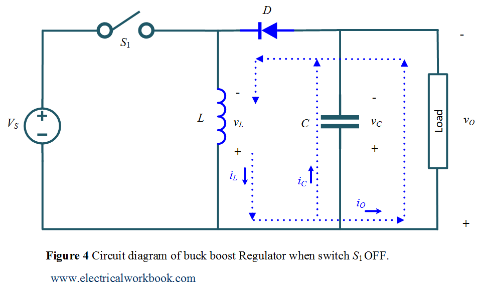
Step Down Chopper with R-L-E Load : Discontinues Current Conduction -  YouTube
Step Down Chopper with R-L-E Load : Discontinues Current Conduction - YouTube

Buck–boost converter - Wikipedia

The Difference between CCM and DCM Explained | Article | MPS

Resources | Powersim, Inc

Discontinuous Conduction Mode of Simple Converters - Technical Articles

SMPS Basics - The Buck Converter

Buck Boost Regulator Average Output Voltage Expression Derivation and Duty  Cycle - ElectricalWorkbook
Buck Boost Regulator Average Output Voltage Expression Derivation and Duty Cycle - ElectricalWorkbook

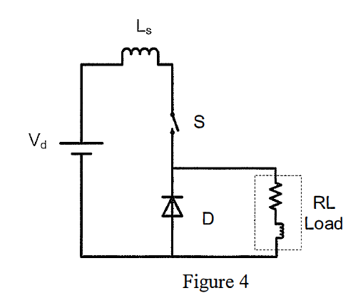
Solved Figure 4 shows the circuit diagram of a buck dc-dc | Chegg.com